How to Draw Section Symbol in Autocad
Working with AutoCAD Mechanical® Symbols in BricsCAD® V22
In BricsCAD® Mechanical V22, we've increased AutoCAD Mechanical® compatibility to make your workflows more streamlined and intuitive. In the following blog, we'll walk you through some of the all-new improvements and show you how they'll increase your productivity when working with AutoCAD Mechanical® symbols.
The first step is to open a drawing in BricsCAD. The first thing you'll see on the screen is the Proxy information window. It informs us that the drawing contains some AutoCAD Mechanical proxies.
You can see the details of this in the information field.
If we close the window and hover over some special symbols, such as welding or the feature control frame it becomes clear they are proxies.
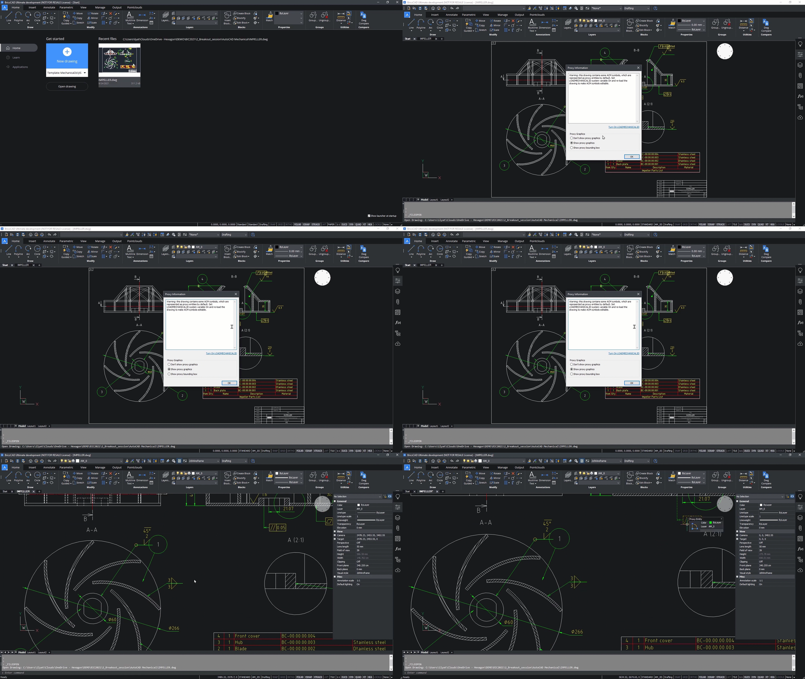
Let's reopen the file and see what can be done in V22.
In the middle of the Proxy information window, you will see a hyperlink that will guide you directly to the LOADMECHANICAL2D setting. This is a user preference setting that controls the demand loading of the Mechanical 2D editor.
Also, in the settings, you can find the MECH2DSAVEFORMAT variable which controls the Mechanical 2d file version.
To apply the load of the Mechanical 2D editor we must reopen the drawing.
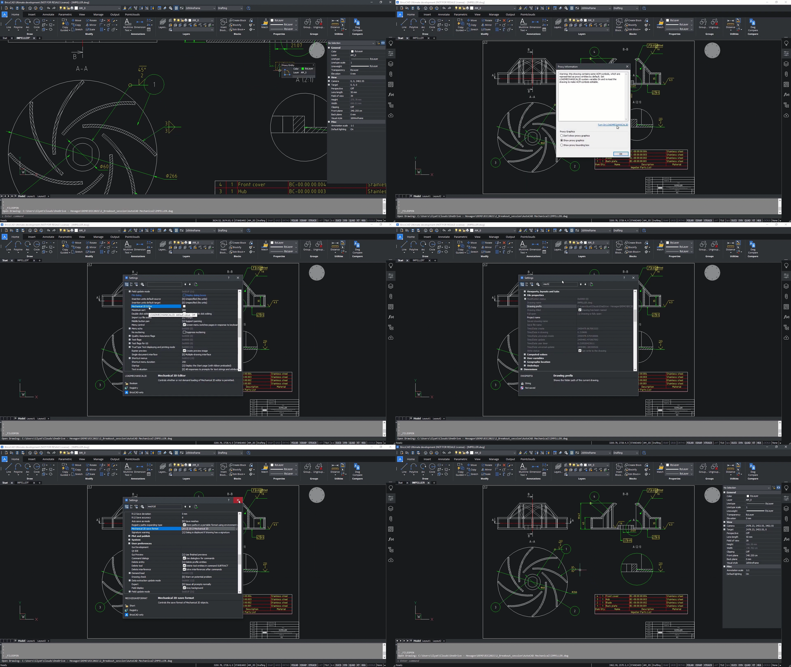
After that, all the AutoCAD Mechanical® symbols are read natively and can be edited.
At this stage, you can review the drawing for any mistakes that may need correcting.
Zooming on the B section and immediately we see an issue -- the welding symbol intersect the dimension line and its alignment is wrong.
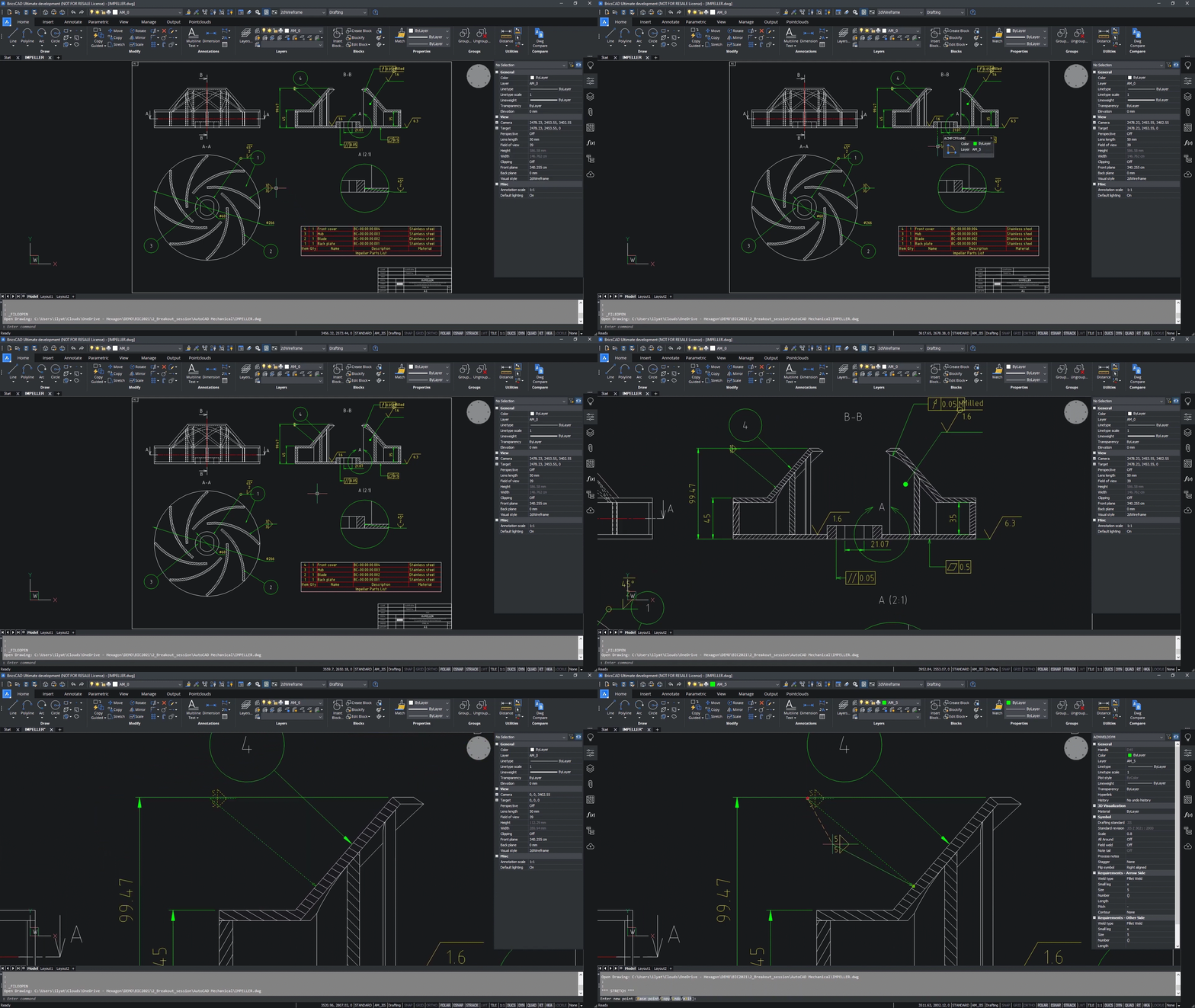
First, we fix the intersection using the Grip Editor. Next, using the properties panel we correct the alignment and increase the scale.
By checking other symbols, we can see other issues. In the GIF below, you can see that we need to avoid the intersection.
The feature control frame is using the wrong symbol. in this case, we want to provide the perpendicularity. This is easy to fix using the properties panel.
In the A section, we see the intersection again. You now know how to fix this issue easily!
Finally, we are not sure that 3 is enough for welding here. We can increase the weld seam size as shown in the GIF below.
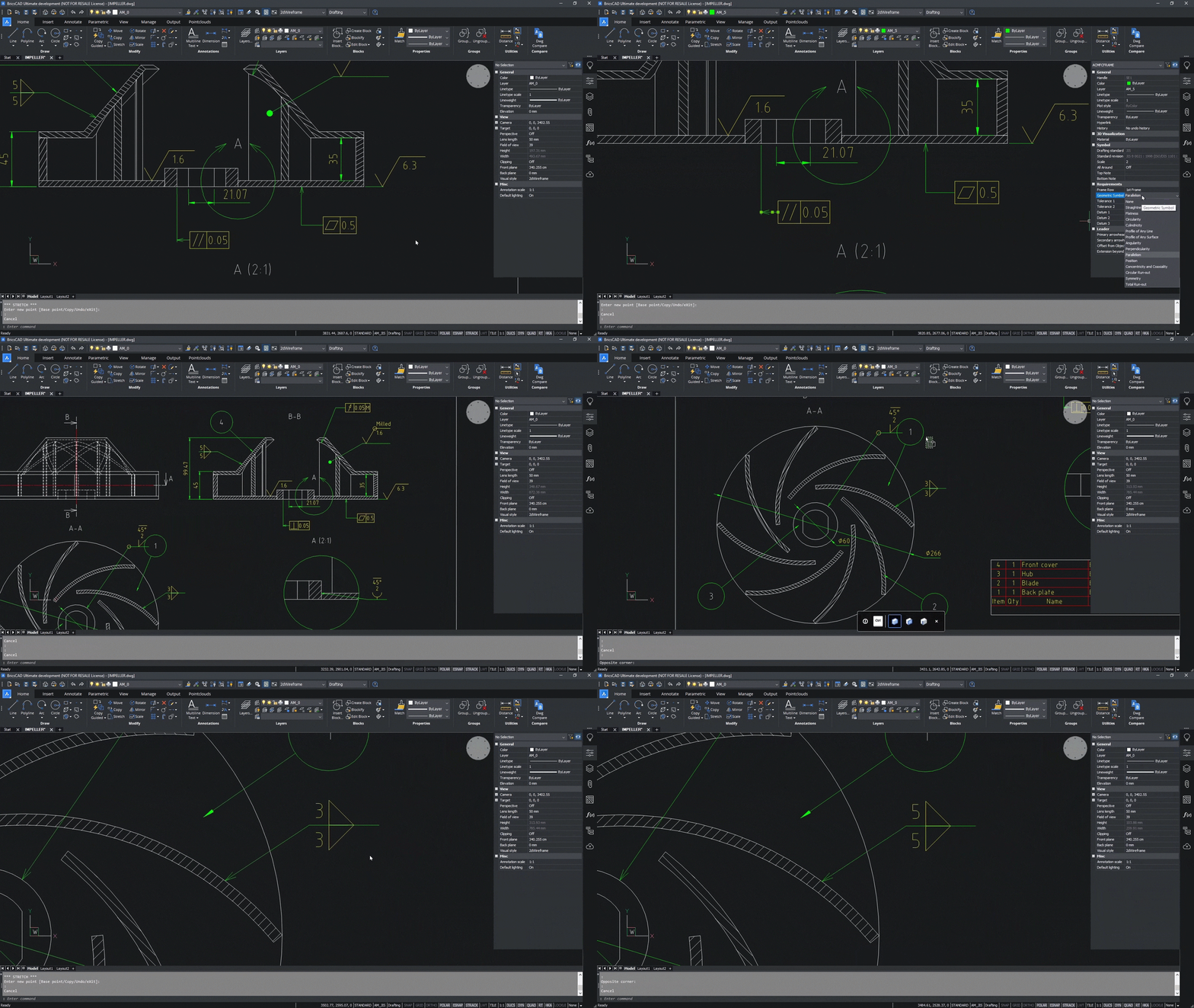
The very small drawing view is the next. In this example, the draftsman made a mistake with the type of welding. The correct type is the Bevel Groove Weld and should be used to weld all around the area.
The part list looks correct but seems there is a misprint. Check out the GIF below for an easy correction.
The final step is to turn the hidden lines layer off.
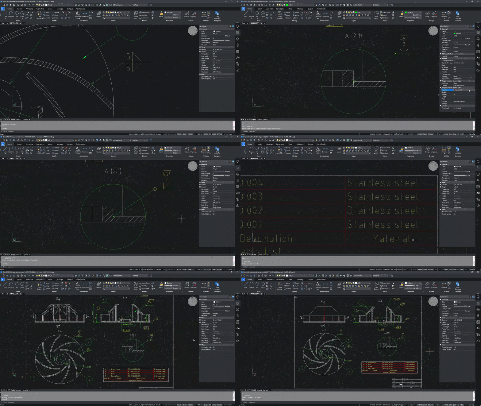
In BricsCAD® Mechanical V22 we are not limited to editing functionality but also can create some special AutoCAD Mechanical® symbols.
To make this possible we'll create a new drawing using one of the templates provided with the BricsCAD installation.
We'll insert the isometric view of the pump frame from the clipboard to add some symbols.
Using the Drafting workspace and annotation tab of the Ribbon we can easily create the welding symbol here. The default symbol does not fit our needs, so it requires some fine-tuning: position, scale, weld size. This can all be done simply and quickly in BricsCAD® Mechanical V22.
If you'd like to know more about working with AutoCAD Mechanical® symbols in BricsCAD® V22 you can check out the full video on the Bricsys YouTube channel.
BricsCAD® Mechanical V22 brings new levels of performance and innovation to the heart of the BricsCAD product family, improving the design, construction, and manufacturing workflows. Discover more about the new and exciting features in BricsCAD® Mechanical V22 here.
hinkleforgerbours.blogspot.com
Source: https://www.bricsys.com/blog/autocad-mechanical-symbols-in-bricscad-v22
0 Response to "How to Draw Section Symbol in Autocad"
Post a Comment